So the issues we had with the gears was not only a matter of spacing, but also a matter of the program not being precise enough. While imaginary gears are possible to make, the ones that we were using from Gearotic do not actually work when cut from plexi-glass. So in order to still use the organic gears we decided to tether them to working gears behind them.
In order to allow the secondary tether to move, a track needs to be cut. This means that we cannot use full rotation servos, as they will not be able to complete a full turn.
After the last attempt we did with milling we noticed that the image of the city wasn't super apparent what the image was at first. The milled effect drew people in more than the specific image. So we were exploring other possibilities with images that could be more ambiguous, like sky, water or trees. Here are some of the images I looked at for research:
As I was researching and looking at these images I was thinking that it would be nice to have something hidden in the trees, like and image:
I pulled some inspiration from this image:
....and started painting:
This is in progress, eventually there will be more trees and I will warp and align the branches to reveal some sort of image.
This will be really cool because even when the gears are not aligned people will be able to tell that they are trees, but until they align the secondary image will be hidden.
For our proof of concept for our final project we wanted to get a working gear train. We were experimenting with some non-traditional gears, and we have two different types we tried. Here is an in progress video of each:
They are not currently fully mounted, so we don't know if the difficulty in it working now is that they are just too loose or what.... we need to experiment further.
I set up a simple test program to try out our gears. It has a continuous rotation servo connected to a potentiometer and a button that turns it all on and off:
Here is the code:
#include <Servo.h>
Servo con;
const int buttonPin = 2;
const int potPin = A0;
int potValue = 0;
int buttonState = 0;
int buttonPressed = 0;
void setup() {
Serial.begin(9600);
con.attach(5);
pinMode(buttonPin, INPUT);
digitalWrite(buttonPin, HIGH);
}
void loop() {
buttonPressed = digitalRead(buttonPin);
buttonPressed = map(buttonPressed,0,1,1,0);//we want a 1 when it's pressed, so we used map to reverse the inputs
if(buttonPressed==1){
buttonState ++;//every time we push the button we increase the button state by 1
delay(500);//make sure we don't push the button to many times by keeping our finger there too long
}
if(buttonState>=2){
buttonState = 0;
}
if(buttonState==0){
con.detach();
}
else if(buttonState==1){
con.attach(5);
potValue = analogRead(potPin); //get value from potentiometer
For our final project our group discussed having sets of gear trains that would be made out of clear gears and visible from the side. These gears would have an image on them which, when they aligned would become viewable as that image. otherwise when the gears aren't aligned the viewer will simply see shapes and designs. For the images to use one of our group member suggested images of the Milwaukee skyline.
I really liked this idea, especially with the water in front of the buildings that gives such great colors and shapes.
I was experimenting with how we might layer the gears. I posted a few comments in the picture.
I felt like we could push this idea further though, and so I tried to think of how we could do this.
I thought it would be cool to have more layers of things going on besides just the buildings and the water. I thought maybe we could add a background image.
I toyed with ideas of what to use for this and I settled on trees or jungle.
I like the idea of the city of Milwaukee eroding away and becoming overgrown by nature. It speaks to time and our relationship with the earth and possibly how civilizations eventually move on and the cities are taken back by nature:
So I did a few quick sketches in Photoshop to get an idea:
With this one I had in mind just the idea of layering civilizations that are separated by so much time and space. Obviously these are very low resolution and I think that we would do some sort of sketch or vectorization of this, but I wanted to see how it might look.
I like the idea of drawing the city as a normal city on one side and as it progresses across it slowly erodes and trees grow over it.
It was really hard to drive my crankshafts with my little servo motor. The first thing I tried was to connect the ends together with a rod like a train wheel.
This didn't work as well as I hoped because the measurements weren't precise enough,
and the cardboard wasn't rigid enough. The rod kept on breaking on me.
I rebuilt the box out of pvc foam and cut gears out of pvc foam to fit a belt that I had.
Tried this method of marking placement first with the teeth on the belt facing in, but this yielded a gear that didn't match up with the belt. When I marked it this way, with the teeth on the belt facing out, the gear meshed smoothly with the belt.
There was too much slack in the belt, so I added a tensioner.
Last minute adjustments to allow it to move more smoothly:
Kept the belt from slipping off.
The gear with the servo on it was farther away from the surface than the other gears,
so I built a mini-ramp to ease it into place.
This worked great until I added all the lights and fiber optics into the mix:
I would like to rebuild this in the future and use stronger material to get it working. The crankshafts were fine, but the housing was too flexible, so when I added the fishing line across the top to keep the led fronds up, it warped the sides. This caused the gears not to run properly and the belt kept falling off. This was also too much strain on the little servo motor I believe.
I would have liked to make this out of clear resin and I would make the all the crankshafts driven by gears. I would have made a band of metal around the top with maybe some metal bracers running in a grid format over the top to keep the shape strong.
I wanted to have flowers that opened and closed. Here are some of the things that I tried in order to accomplish this:
At first I thought that if I just had the flower material retract into the cone that it would spring back up when pushed out, but the material wanted to keep its form as it was inside the cone.
Next I tried to make it all out of the same strip of material so that it would pull the rest up as it was pushed out:
I did not like the corkscrew effect that this had.
Next I tried making loops out of fishing line that would be tethered to the cone on one end and be attached to the wire on the other. This would make the "petals" expand as the wire was pushed up:
This was not successful as the material did not fit down into the tube.
The final thing I tried was again with the fishing line. I simply tethered four pieces of fishing line to the copper wire so that they would push up as the wire pushed up. The line has a natural curve caused by the spool it came on:
I tried six strings at first, but then it had trouble fitting down the tube, so I went down to only four.
My plan was to attach a sort of webbing to these so that it would pull in and out as the fishing line moved in and out.
I started out by making the cranks I wanted the LED fiber optic grass bundles to ride on.
I needed something to attach the bundles to so that they could always remain upright on the rotating crankshaft. I used this plastic tubing I bought for the flower stems.
I attached the leds in sets of three to a piece of tubing that I slit down the side so that it would sit on top of the tubing attached to the cranks:
I then soldered wires on to the bundles:
I hot glued my fiber optics bundles to the top of them:
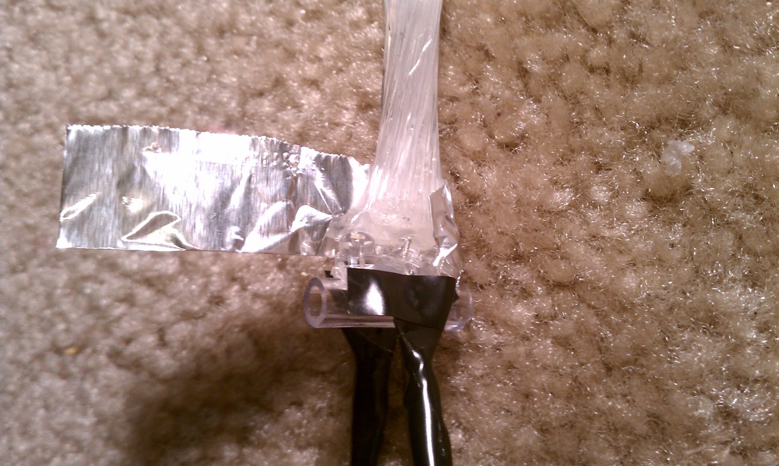
I used tin foil wrapped around the base to direct the light up the fiber optics, instead of being diffused at the base:


.jpg)


 Obviously these are very low resolution and I think that we would do some sort of sketch or vectorization of this, but I wanted to see how it might look.